This article is about a 5-phase bipolar stepper motor that I happened to come across. I have also written a related article about an H bridge that I built to drive this motor.
There is a lot written about stepper motors on the internet and I will not repeat too much of that in this article. Here are two good links:
So, the motor that this text is about is a 5-phase bipolar motor. This is a high-end kind of stepper motor that requires relatively complex drive circuitry and provides a lot of torque for its size and a high step resolution.
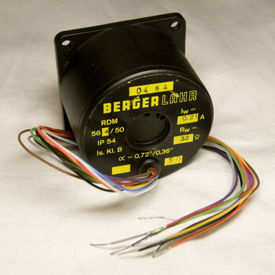
A photo of the back side of this motor is shown in figure 1 below.
The text and my comments are:
| Text | Comment |
|---|---|
| 0484 | Maybe the batch number |
| BERGER LAHR | The manufacturer logo, Berger Lahr seems to be owned by Schneider Electric nowadays |
| RDM 564/50 | Maybe the model number |
| IP 54 | The IP classification; 5 = dust protected, 4 = splashing water protected |
| Is. Kl. B | Maybe the NEMA insulation class; B = maximum 130°C winding operating temperature; 80°C allowable temperature rise at full load (at 40°C with 10°C hot spot margin). |
| IW = 0,21 A | Rated winding current |
| RW = 32 Ω | Winding resistance |
| α = 0.72°/0.36° | Step size, full step = 0.72°, half step = 0.36° |
With 0.72° step size, the motor has 500 full steps per revolution, which is quite impressive. Unfortunately, I have not been able to find any information about this motor from the website of Schneider Electric which now apparently owns Berger Lahr, so the information necessary to use the motor (in addition to what can be read from the plate) has to be found out by experimentation.
There are ten wires with different colors coming out of the motor and it is easy to ohm them to figure out which ones connect to the same winding. It is a little bit trickier however to figure out in what order the windings are positioned inside the motor. The way I did find out was to attach a long pointer to the motor shaft and to in turn connect the various windings to a power supply. Often this would produce a relatively large jump in the pointer, but sometimes the motor took just a small step. When this happened I noted which two windings were involved and the direction of current in the windings, since the small step means that the windings are adjacent. The table below shows the results of the experiment.
| Winding # | Positive terminal | Negative terminal |
|---|---|---|
| 1 | white | yellow |
| 2 | brown | purple |
| 3 | black | gray |
| 4 | orange | green |
| 5 | red | blue |
I wanted to know the holding torque of the motor, so I put the motor with the shaft horizontal. Then I attached a horizontal lever at right angle to the shaft and hanged a little bottle at the end of it (16 cm from the center of the axis). I then ran current through one of the windings and started to slowly fill the bottle with water until the motor could no longer hold it. I then weighed the bottle and could thereby calculate the holding torque. I repeated the experiment with 2, 3, 4 and 5 windings powered. The results can be seen in the table below.
| # of powered windings | Holding torque |
|---|---|
| 1 | 64 mNm |
| 2 | 121 mNm |
| 3 | 170 mNm |
| 4 | 214 mNm |
| 5 | 231 mNm |
The data is visualized in figure 2 below.
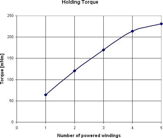
It seems like the torque increases almost linearly from 1 to four windings, but powering also the fifth winding gives less of an increase in torque.
Using H bridges I developed as described in another article and a PICDEM FS USB development board, I was able to run the motor. A short movie clip showing the motor turning slowly is provided below.
There are lots of room for improvement and sophistication in the motor drive. One thing that could be interesting to look into is to use micro-stepping to reduce the vibrations when running the motor (especially at low speeds).
Another thing is to build a more advanced drive that uses a higher voltage when turning a winding on to increase the torque and maximum speed.